
TM 5-3805-274-13&P
0038
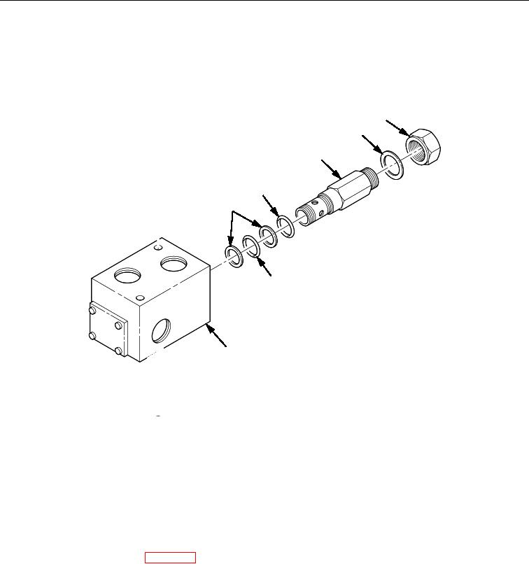
DISASSEMBLY
1. Remove cap (Figure 1, Item 5) and metal gasket (Figure 1, Item 4) from relief valve body
(Figure 1, Item 3).
2. Remove relief valve body (Figure 1, Item 3) from pilot relief valve housing (Figure 1, Item 7).
3. Remove two backup rings (Figure 1, Item 1) and two O-rings (Figure 1, Items 2 and 6) from relief valve
body (Figure 1, Item 3). Discard backup rings (Figure 1, Item 1) and O-rings (Figure 1, Items 2 and 6).
5
4
3
2
1
6
7
Figure 1. Pilot Relief Valve Disassembly and Assembly.
END OF TASK
ASSEMBLY
1. Install two new O-rings (Figure 1, Items 2 and 6) and two new backup rings (Figure 1, Item 1) on
internal side of relief valve body (Figure 1, Item 3).
2. Install relief valve body (Figure 1, Item 3) in pilot relief valve housing (Figure 1, Item 7).
3. Install metal gasket (Figure 1, Item 4) on cap threads.
4. Install cap (Figure 1, Item 5) on relief valve body (Figure 1, Item 3).
5. Install pilot relief valve (WP 0037).
END OF TASK
END OF WORK PACKAGE