
TRUCK SERVICE MANUAL
TRANSMISSION
Para 7-17/7-18
HT 700D SERIES TRANSMISSION
b. Oil Filter, Oil Pan
(1) Install the sealring onto the oil intake pipe (fig. 7-50).
Lubricate the sealring with oil-soluble grease.
(2) Install the oil filter making sure the intake pipe fits
snugly into the housing (fig. 7-50). Do not twist the
oil filter during installation push straight inward.
(3) Retain the oil filter with one 5/16-18 x 5/8-inch,
washer headscrew and a spacer between the filter
and valve body (fig. 7-51). Tighten the screw to 10
to 13 pound feet (14 to 18 N.m) torque.
(4) Install two 5/16-18 x 3-inch guide screws 38 (fig. 4-
3) into the transmission housing (fig. 7-51).
(5) Install a new oil pan gasket over the guide screws.
Aline all holes in the gasket with those in the housing
(fig. 7-51).
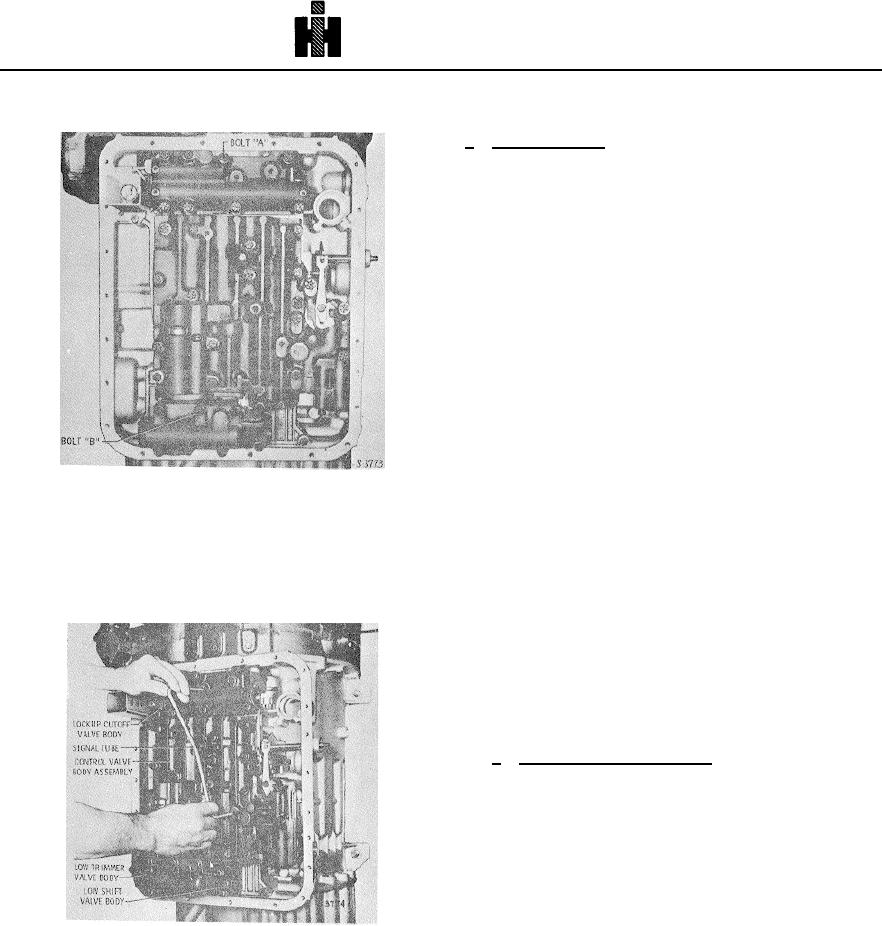
Fig. 7-56 Valve body assemblies (HT750)
NOTE
(9) Hold the detent in alinement over the detent
lever while the 2 1/2-inch bolt is tightened to 8 to 12
Do not apply grease or any type of sealer to the oil
pound feet (11 to 16 Nm) torque. Tighten all (38) of the
pan gasket except in the area outside the bead on
bolts to 8 to 12 pound feet (11 to 16 Nm) torque.
the oil pan flange.
(10)
Install the signal tube (fig. 7-57).
(6) Install 'the oil pan (fig. 7-51). Install twenty-three
5/16-18 x 5/8-inch, washerhead screws (fig. 7-52).
Tighten the screws evenly to 10 to 13 pound feet (14
to 18 N.m) torque.
7-18.
INSTALLING FLYWHEEL,
LOCKUP CLUTCH, TORQUE
CONVERTER TURBINE
a. Aline Flywheel for Installation
(1) Position the transmission horizontally (fig. 7-58).
(2) Place the flywheel assembly (as assembled in
para 6-3) on a work table, ring
Fig. 7-57 Installing signal tube (HT750)
787

