
TRUCK SERVICE MANUAL
ENGINE
5. Lift rod, arbor and pin assembly from fixture; turn
horizontally 180 deg; set back in fixture. Readjust dial
indicators to divide difference between first and second
readings; fixture is now calibrated.
Check Rod Alignment
1. Measurements read directly from dial indicator indicate
comparative
length
and
misalignment
of
bores.
Measurements apply with or without bushing installed.
2. Assemble ST-563 Mandrel Set in rod to be checked.
Set rod in fixture; be sure pin in mandrel is down and locked in
position in center line of rod.
3. Take readings for length (compared to length set up in
calibration of fixture) and misalignment of bores (difference
in reading from one indicator to other).
2. Parting Line
4. Turn rod 180 deg. Total reading must not exceed
Fig. 1-8 (N10194) . Connecting rod wear limits
0.008 inch [0.20 mm] when connecting rod does not contain
bushing or 0.004 inch [0.10 mm] with bushing installed and
bored to size. This is combined plus and minus readings of
b. On 2 bolt connecting rods, bore diameter must be
indicator. Length must read 0.001 inch [0.03 mm] on gauges.
within 3.2722 to 3.2732 inch [83.114 to 83.139 mm] beyond 30
deg. on either side of parting line.
5. Measure rod twist with a feeler gauge between piston
pin and dial holding plate. When measuring connecting rod
twist in ST-561 and rod does not contain piston pin bushing,
c. If either specification is not met, the rod must be
twist must not exceed 0.020 inch [0.51 mm]. Twist must not
resized.
exceed 0. inch [0.25 mm] with bushing in place and bored to
4. Gauge piston pin bushing diameter with ST-205 Plug
size.
Gauge or with inside micrometer. See Table 1-1 (11).
Check Bolts, Bolt Holes And Bolt Pads (2 Bolt Rod)
5. Use ST-561 Checking Fixture and ST-563 Locating
1. The bolt head must rest squarely on milled surfaces of
Mandrel to check rod alignment.
rod.
2. If connecting rod bolts have been tightened
Calibrate ST-561 Checking Fixture For Rod Size
excessively
1. Select a new rod that has been checked for correct
absolute center to center length, 12 inch [304.80 mm] between
centers. Production rods may vary from 11.998 to 12.000 inch
[304.75 to 304.80 mm] .
2. Assemble cap to rod as described in Step 2 under
Inspection.
3. Insert piston pin, furnished in ST-563 Mandrel Set, in
piston pin bore. Insert and tighten ("snug" only) expanding
arbor in crankpin bore.
CAUTION
The expanding arbor must be installed with locking
pin down and on center line of rod.
4. Set rod in fixture and move dial holder so dials
indicate on piston pin. Zero dial indicators.
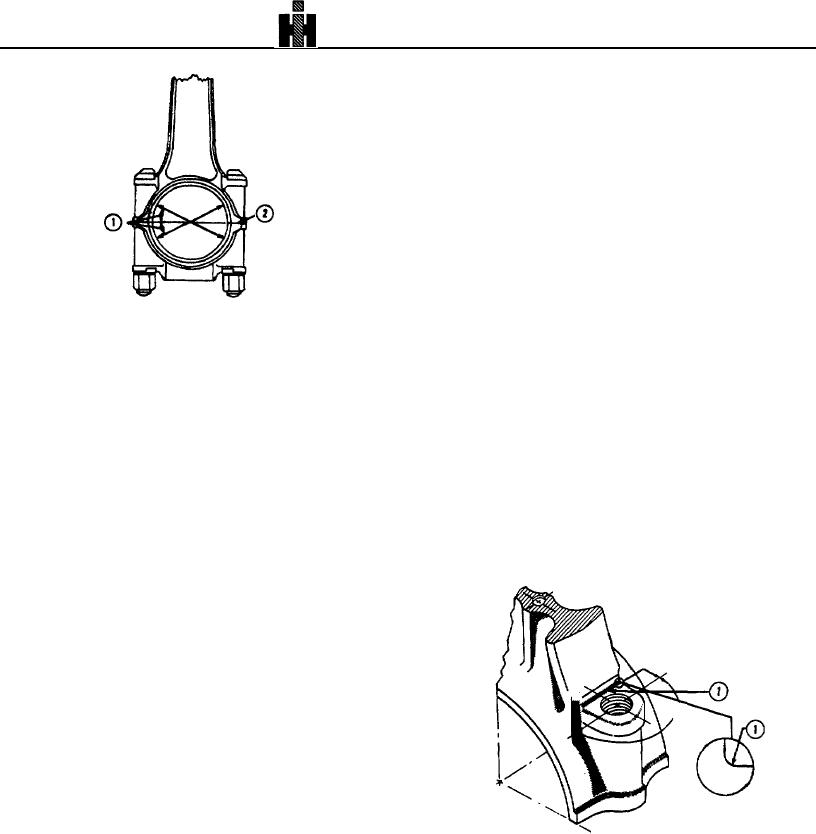
1. Bolt Head Fillet Radius
Fig. 1-9 (N40114A) Connecting rod radius specifications.
338