
TRUCK SERVICE MANUAL
ENGINE
a. Hold ring in groove, flush with land and insert 0.006
2. Be sure rod and cap are stamped with cylinder number
inch [0.15 mm] feeler gauge.
from which removed before disassembly to prevent mixing
parts.
b. If gauge enters groove without forcing or disengaging
ring, wear is excessive and piston should not be used.
3. Install one piston pin snap ring in groove of piston pin
bore.
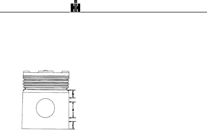
3. Measure piston skirt diameter with micrometer at right
4. Heat aluminum pistons in boiling water or in an oven at
angle to piston pin bore (A, Fig. 1-11 for barrelground pistons);
or below 210 deg. F [98.9 deg. C] and install pin through
measure straight or tapered ground pistons at Point B, 1 inch
piston and connecting rod pin bores before piston cools; at 70
[25.4 mm] below ring groove and C, 1 inch [25.4 mm] above
deg. F [21 deg. C] the pin fit is 0.0001 to -0.0003 inch [0.003 to
bottom of piston. Pistons should not be reused if worn more
-0.008 mm] which prevents pin assembly unless piston is
than 5.483 inch [139.27 mm].
heated, Secure pin with second snap ring in groove at
opposite end of pin bore.
CAUTION
Never drive piston pin in pistons. Driving may cause
distortion of piston, causing piston seizure in cylinder
liner.
REAR COVER
The rear cover is a unit subject to replacement of seals only.
Damaged housings require replacement by a new assembly or
installation of a "Heli-Coil" for stripped threads; these are only
items of repair.
Alignment during engine assembly is the biggest factor for
proper performance of the rear cover unit. See Group 14.
CAMSHAFT
INSPECTION
Check camshaft bushing journals with micrometers.
a. Pin Bore Area
Replace camshaft if journals are worn beyond limits given in
b. Area Below Ring Groove
Table 1-1 (15).
c. Piston Skirt
Replace camshafts that have scuffed, scored, or cracked
Fig. 1-11 (N20171) Piston check points.
injector or valve lobes. Check by magnetic inspection for
4. Pistons should be checked at temperature of 70 to 90
possible cracks.
deg. F [21 to 32 deg. C]. After measuring piston and
Cummins Engine Company, Inc.
does
not
recommend
comparing with liner inside diameter, piston-to-liner
regrinding of camshaft lobes.
clearance may be computed if desired.
Camshaft Support
5. Piston pin bore checked at 70 deg. F [21.1 deg. C]
If cast iron support is used, inspect bushing in support;
should fall within limits shown in Table 1-1; add 0.0005 inch
remove if damaged or worn smaller than 1. inch [34.80 mm];
[0.013 mm] per 10 deg. F [-12 deg. C] up to 90 deg. F [32 deg.
press in new bushing flush with inner bore. New dimensions
C] .
are 1.3725 to 1.3755 inch [34.86 to 34.93 mm]. Replace
aluminum support.
6. Check piston pin outside diameter with micrometer.
Pins should not be reused if out-of-round more than 0.001 inch
[0.03 mm] or worn smaller than indicated in Table 1-1 (13).
Thrust Bearing
Reboring of piston pin bores and use of oversize pins is not
Inspect thrust bearing for flaking, burrs, distortion and
practical because the misalignment that results from such
practice will cause seizure of piston or failure of connecting rod
Piston-To-Connecting Rod Assembly
1. Pistons are machined to a very close weight tolerance;
therefore, as long as the same part number piston is used
throughout the engine, weight does not affect engine
operation.
341