
TRUCK SERVICE MANUAL
ENGINE
Note: The above measurement is boring dimension before rod
they may be permanently stretched, in which case they must
and cap separation.
be discarded. Discard bolts if smallest diameter is less than
listed in specifications.
4. Check alignment on ST-561.
See "Check Rod
Alignment".
3.
Discard all bolts and nuts that have distorted threads.
Note: ST-294 Boring Machine is not suitable for this job.
4. Check rod bolt hole pilot inside diameter in rod and
Use ST-526, a milling machine or cylinder grinder with a
cap. If diameter exceeds wear limits, discard rod and cap.
precision fixture. Finished surface must be to 75 micro-inch or
5.
Check bolt pad radius. See (1-Fig. 1-9).
better to insure proper contact with connecting rod bearing
shells.
REPAIR
5. Install and bore new heavy-wall piston pin bushing as
described under "Replace Piston Pin Bushing". Heavy-wall
Restore Fillet
special bushing, Part No. 1'52770, must be used, Bore piston
1. A dimension of 0.045 to 0.055 inch [1.14 to 1.40 mm]
pin bushing off-center to restore rod to original 11.998 to
(2 bolt rod 1, Fig. 1-9)(0.240 to 0.260 inch [6.10 to 6.60 mm] 4
12.000 inch [304.75 to 304.80 mm] length.
bolt rod) fillet radius must be present at all corners where rod
Replace Piston Pin Bushing
is milled for bolt head. Maximum 1/16 inch [1.59 mm] metal
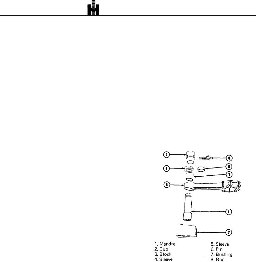
1. Remove worn tapered bushings with ST-1242 Mandrel
may be milled off to restore radius.
and Detail (5, Fig. 1-10), remove tool.
2. Remove nicks and dents which are less than 1/16 inch
2. To install standard size tapered bushing (7) in rod,
[1.59 mm] deep by grinding or filing with a half-round file.
assemble bushing (7) on Mandrel (1), position Sleeve (4) then
Radius must be 1/2 inch [12. mm] or more, Blend radii at ends
Cup (2) on Mandrel (1). Secure with Locking Pin (6).
of cut. Scrap rod if dents are deeper than 1/16 inch [1.59 mm]
3. Place connecting rod on Block (3) and support in
(3, Fig. 1-6).
horizontal position.
Resize Crankpin Bore
Resize only if crankpin bore is outside limits given in Table 1-1
(11).
1. Remove old piston pin bushing with ST-870 Mandrel
and Block. Install cap and tighten nuts to operating tension.
2. Recheck rod length on ST-561 Checking Fixture, If rod
length is 11.991 Inch [304.57 mm] or less, rod cannot be
resized and must be discarded.
Note: Rod must measure 12. inch [304.80 mm] in length to
remove 0.009 inch [0.23 mm] from mating surfaces of cap and
rod face.
a. Parts must be clamped securely during operation to
insure proper contact of entire mating surfaces and proper
alignment of bores for rod bolts when assembled. Bolt holes
must remain perpendicular to machined mating faces.
b. Use surface plate and lapping compound to lap rod
and cap mating surfaces. After grinding and lapping, "blue"
surfaces; seating or flatness pattern must show a minimum
75% contact. Still-blued area must not be in area outside bolt
centerline (area farthest from bore centerline); this area should
indicate 100% seating.
c. Place mating rod and cap surfaces together and check
closely for evidence of out of flat.
3. The rod cap must be reassembled to rod and
Fig. 1-10. (N10158) Installing piston pin bushing in rod.
tightened to operating tension. On 2 bolt rod line bore or grind
crankpin bore to 3.2720 to 3.2725 inch [83.119 to 83.134 mm]
inside diameter.
339