
TRUCK SERVICE MANUAL
ENGINE
2. Loosen locknut and back off adjusting screw. Insert
Rocker Housing Covers
feeler gauge between rocker lever and crosshead. Valve
Position covers and gaskets on rocker housings or
clearances are shown in Table 14-13. Turn screw down
Jacob's Brake. Tighten all cover capscrews using
until lever just touches gauge and lock in this position.
combination cork and rubber gaskets to 75 to 95 inch-lb.
Fig.14-31. Tighten locknut to 30 to 40 ft-lb. [4.1 to 5.5 kg
[0.9 to 1.1 kg ml, tighten all cover capscrews using cork
m] torque. When using ST-669 torque to 25 to 35 it-lb.
gaskets to 12 to 17 ft-lb. [1.7 to 2.4 kg ml torque.
[3.5 to 4.8 kg mi.
Note: Check current Parts Catalog for correct cover-
3. Continue to bar engine to next "VS" mark and adjust
gasket combination.
each cylinder in firing order. See Table 14-10. After
injector and valve adjustment is completed, bar or crank
Breather Tube
(in chassis overhaul) engine several revolutions to
Install breather tube, if used, to rocker housing cover and
secure to block with clamp.
Table 14-13: Valve Clearance - Inch [mm] (Torque
Cranking Motor
Method)
1. Check cranking motor; see that it is the same type as
Intake Valves
Exhaust Valves
removed. Cranking motors are designed with different
Cold Set
Hot Set
Cold Set
Hot Set
type drives and must be used with a matching flywheel
ring gear.
Aluminum Rocker Housing
0.014
0.014
0.027
0.027
2. Mount cranking motor (and spacer if used) to flywheel
[0.36]
[0.36]
[0.69]
[0.69]
housing.
Cast Iron Rocker Housing
Note: When wet type clutch is used, use "O" rings and
Nylok capscrews when installing starter.
0.016
0.014
0.029
0.027
[0.41]
[0.36]
[0.74]
[0.69]
Water Filter
1. Secure water filter head to engine, or mounting
bracket, attach shut-off valves and lines in proper
position.
2. Install pre-charge element, tighten until seal touches
filter head then tighten an additional 1/2 to 3/4 turn.
Turbocharger
1. Coat turbocharger mounting stud or capscrew threads
with anti-seize compound. Place gasket on exhaust
manifold with convex side toward turbocharger.
2. Install turbocharger to exhaust manifold and secure
with hug-lock nuts. Oil drain line must always be in a
vertical or down position or within 30 deg. of that position.
3. Connect No. 6 oil inlet line or equivalent size tubing
from top of turbocharger to oil cooler or transfer housing.
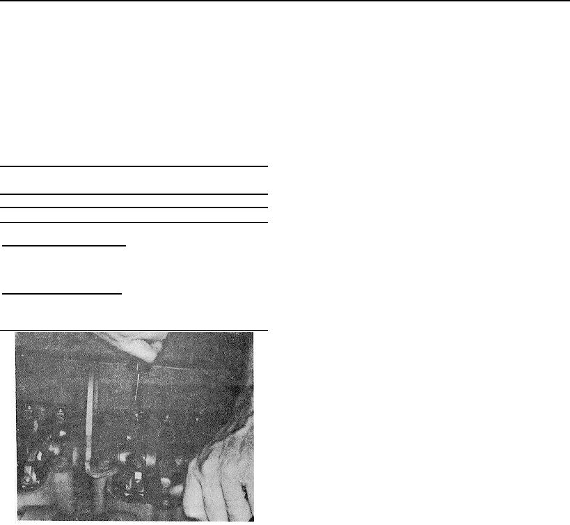
Fig. 14-31, (N114215). Adjusting valves
4. Connect No. 16 oil drain line or equivalent size tubing
from turbocharger to large boss on side of cylinder block.
properly seat adjusting screws, plunger links, push tubes,
etc. to mating surfaces. Take break-away torque reading
Note: If turbocharger "vee clamp" is loosened to align oil
on injector plunger adjusting screws. Break-away torque
drain line, tighten to 32 to 36 inch-lb. [0.37 to Q.41 kg ml
must be the same as adjustment torque. See Table 14-
torque.
12. Re-adjust as necessary.
5. Install air intake crossover between turbocharger outlet
Jacob's Brake
and air intake manifold or aftercooler. Install new rubber
tubing connection and T-bolt type clamps.
Install Jacob's Brake, if used. See Group 20.
410