
TRUCK SERVICE MANUAL
ENGINE
Note: If generator or alternator pulley has been removed
or a new pulley is installed, use hardened steel washer
and locknut. Torque to values in Table 14-8.
Table 148: Torque Values (Pulley to Alternator or
Nominal Thread Size
Torque
Inch
Ft-Lb [Kg m]
1/2
50 to 60
[6.9 to 8.3]
5/8
55 to 65
[7.6 to 9.0]
3/4
90 to 100 [12.4 to 13.8]
Note: Exception to the above limits are:
1. Belt Deflection
Delco-Remy
Torque
2. Belt Free Span
Ft-Lb [Kg ml
1 0 DN 150
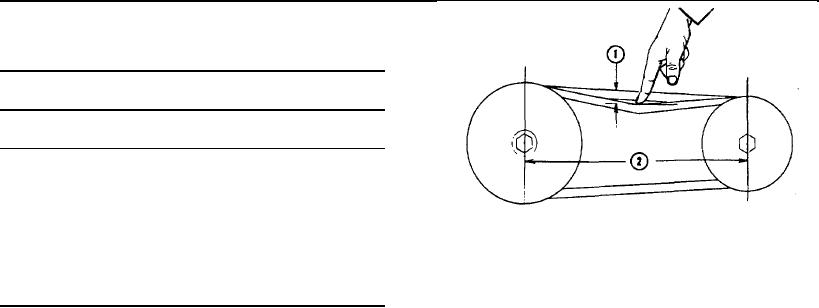
Fig. 14-24, (N11471). Checking belt tension manually
25 SI
70 to 80
[9.7 to 11.1]
Belt Tension
ADJUST INJECTORS, CROSSHEADS AND VALVES
1. Installation:
Before adjusting injectors and valves be sure to
2.
determine if rocker housings are cast iron or aluminum
a. When two or more identical belts are used on the
and use appropriate setting.
same drive, they must be replaced as a matched set.
Two methods of adjusting injectors and valves are
b. Shorten distance between pulley centers and install
described in this manual. The preferred method is
belt(s). Do not roll or pry belt over pulley.
Uniform Plunger Travel. This method involves adjusting
plunger with ST-1270 Injector Indicator Kit (consists of
c. Pulley misalignment must not exceed 1/16 inch [1.59
ST-1170 Dial Indicator, ST-1 193 Actuator and ST-1251
mm] for each foot [304.8 mm] of distance between pulley
Actuator) to a specified travel. The second method
centers.
involves setting plunger adjusting screw to a specified
torque setting. It is essential that injectors and valves be
d. Belts should not bottom on pulley grooves, nor should
in correct adjustment at all times.
they protrude over 3/32 inch [2.38 mm] above top edge
of groove.
Injector "Plunger Free Travel," as described below, must
be checked before adjustments are made.
e. Belt riding depth should not vary over 1/16 inch [1.59
mm] on matched belt sets.
Check Plunger Free Travel
f. Do not allow belts to rub against any adjacent part.
In order to prevent excessive loading of injector actuating
train and possible failure, check as follows:
2. Adjusting:
1. Back injector adjusting screw out 1-1/2 turns from
a. Use ST-968 for 3/8 to 1/2 inch [9.53 to 12.70 mm]
normal operating position, tighten locknut.
width belts. Use ST-1138 for 11/16 to 7/8 inch [17.46 to
22.23 mm] width belts.
2. With ST-1170 Dial Indicator extension on injector
plunger top, bar engine and record total amount of each
b. When belts are installed, tighten until a reading of 90
plunger travel. This is called "Plunger Free Travel" and
to 110 lb. force is obtained. New belts will loosen after
MUST NOT exceed 0.206 inch [5.23 mm] on any one (1)
running for an hour or more and may require re-
cylinder of engine.
adjustment. Recheck belt tension and re-adjust to 90 to
110 lbs. if reading is less than 80 lbs.
3. On engines with plunger Free Travel exceeding 0.206
c. As an alternate method, tighten belts so pressure of
inch [5.23 mm] the Torque Method of adjustment must
index finger extended straight down, Fig. 14-24 will
be used unless component changes (rocker levers
depress belt to the value shown in Table 14-5. Force
and/or cam followers) are made which will allow 0.206
applied (1) will be approximately 13 lb. [5.9 kg] for each
inch [5.23 mm] limit of Free Travel to be obtained.
foot
[0.30
ml
of
free
span
(2).
406