
TRUCK SERVICE MANUAL
ENGINE
1. Turn adjusting screw down until plunger contacts cup
Valve Adjustment
and advance an additional 15 degrees to squeeze oil
from cup.
The same engine position (VS Mark) used to adjust
injectors is used for setting intake and exhaust valves,
2. Loosen adjusting screw one turn; then, tighten
however, the valves to be adjusted are not the same
adjusting screw making two or three passes with torque
cylinder as injectors. In this position adjust valves for
wrench, to values shown in Table 14-12.
cylinder No. 5. See Table 14-9.
1. While adjusting valves, make sure compression
release, on those engines so equipped, is in running
position.
2. Loosen locknut and back off adjusting screw. Insert
feeler gauge between rocker lever and crosshead. Valve
clearances are shown in Table 14-11. Turn screw down
until lever just touches gauge and lock in this position.
Tighten locknut to 30 to 40 ft-lb. [4.1 to 5.5 kg m] torque.
When using ST-669, torque to 25 to 35 ft-lb. [3.5 to 4.8
kg m]
3. Always make valve adjustment after injector
adjustment. Move to next cylinder as indicated in Table
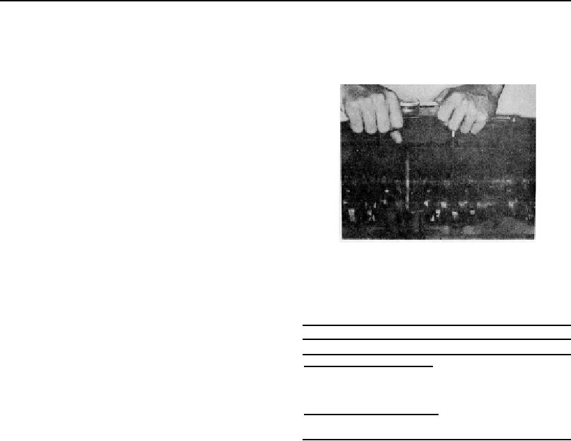
Fig. 14-30, (N1 1466). Adjusting injector plunger
14-9 and repeat adjustments.
Note: Set ST-753-1 Torque Wrench on value required
ADJUST INJECTORS AND VALVES
and pull to "O". Break adjusting screw loose and pull
(TORQUE METHOD)
torque to value shown on each tightening pass.
1. If used, pull compression release lever back and block
Table 14-12: Injector Adjustment (Oil Temperature)
in open position while barring engine, this allows
Cold Set
Hot Set
crankshaft to be rotated without working against
Cast Iron Rocker Housing
compression.
48 inch-lb
72 inch lb.
[0.6 kg ml
[0.8 kg ml
2. Loosen the injector rocker lever adjusting nut on all
cylinders. This will aid in distinguishing between cylinders
Aluminum Rocker Housing
adjusted and not adjusted.
72 inch-lb
72 inch-lb
[0,8 kg ml
[0.8 kg ml
3. Bar engine in direction of rotation until a valve set
mark (Fig's. 14-25 and 14-26) aligns with the boss on the
3. Tighten locknut to 30 to 40 ft-lb. [4.1 to 5.5 kg ml
gear case cover. Example: A or 1-6 "VS."
torque. If ST-669 torque wrench adapter is used, torque
to 25 to 35 ft-lb. [3.5 to 4.8 kg mi.
4. Check the valve rocker levers on the two cylinders
aligned as indicated on pulley (Example: 1 and 6
Croshead Adjustment
cylinders for A or 1-6 "VS"). On one cylinder of the pair,
both rocker levers will be free and valves closed, this is
See Crosshead Adjustment (Dial Indicator Method)
cylinder to be adjusted.
Valve Adjustment - Torque Method
5. Adjust injector plunger first, then crossheads and
valves to clearances indicated in the following
The same engine position used in adjusting injectors is
paragraphs.
used for setting intake and exhaust valves.
Injector Plunger Adjustment - Torque Method
1. While adjusting valves, make sure that the
compression release, on those engines so equipped, is
The injector plungers are adjusted with a torque wrench
in running position.
and a screwdriver adapter to a definite torque setting.
See Fig. 14-30.
409