
TRUCK SERVICE MANUAL
ENGINE
2. Align capscrew holes and install pulley and vibration
c. Final torque in rotation to 30 ft-lb. [4.1 kg m] .
damper assembly to crankshaft, tap into position with soft
hammer. Coat capscrews with clean lubricating oil,
2. Position belts over water pump, idler and accessory
secure pulley and damper assembly to crankshaft torque
drive pulleys. Tighten idler adjusting screw to obtain, 120
to 85 ft-lb. [11.8 kg m].
to 140 lb. belt tension using ST-968 or ST-1274 Belt
Tension Gauge.
3. Secure idler shaft to bracket with flatwasher and
Note: Check capscrew marking, if '1/2 inch Grade 8
locking nut. Tighten to 50 ft-lb. [6.9 kg ml torque. Back off
capscrews are used tighten capscrews to 115 to 125 ft-
adjusting screw 1/2 turn.
lb. [15.9 to 17.3 kg m] torque. If 5/8 inch Grade
4. If not previously installed, position fan hub assembly to
capscrews are used tighten to 210 to 240 ft-lb. [29.0 to
mounting bracket. Tighten capscrews finger tight.
34.0 kg m] torque. See Capscrew Markings and Torque
5. Position and secure fan hub assembly and bracket to
Values,
water pump housing.
6. Secure fan bracket support to fan bracket and install
3. If vibration damper was removed from pulley, wipe
adjusting screw and hardened washer (if used).
mating surface of damper and pulley clean, position
7. Position belts over fan hub pulley and accessory drive
damper to pulley, install and torque capscrews to 85 ft-lb.
pulley, tighten fan hub adjusting screw to obtain 90 to
[11.8 kg mi.
110 lb. belt tension using ST-968 or ST-1138 Belt
Tension Gauge.
4. Check damper for eccentricity and wobble as
8. Secure fan hub assembly to fan mounting bracket,
described in Step 5 preceding.
torque capscrews to 50 ft-lb. [6.9 kg m] .
Accessory Drive Pulley
Fan Hub And Pulley
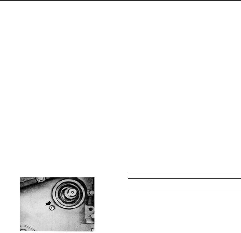
Note: Remove pipe plug in gear cover, check to make
1. Assemble fan pulley to fan bracket, if not previously
sure timing marks are lined up, Fig. 14-22. Replace pipe
installed. Position flatwasher and locking nut on shaft.
plug.
Start nut on thread, do not tighten.
1. Install oil slinger over accessory drive shaft, with key
2. Avoid stretching belts, loosen adjusting screw, position
and keyway seal, if used, on accessory drive shaft.
belts over fan hub and drive pulleys.
Lubricate shaft with clean lubricating oil, start accessory
drive pulley over shaft and key; use ST-386 to position
3. Tighten adjusting screw to obtain proper tension of
pulley on shaft.
drive belts. See Table 14-5.
2. Remove ST-386; install flatwasher and pulley nut.
Torque nut to 90 to 110 ft-lb. [12.4 to 15.2 kg ml]
Table 14-5: Belt Tension Inch [mm]
Deflection Per Ft.
Belt Width
[0.3 m] of Span
1/2
[12.70]
13/32 [10.14]
11/16 [17.46]
13/32 [10.14]
3/4
[19.05]
7/16
[11.11]
7/8
[22.23]
1/2
[12.70]
1
[25.40]
9/16
[14.29]
4. Torque fan hub shaft-to-bracket nut to 400 to 450 ft-lb.
[55.3 to 62.2 kg m]. Do not overtighten. Back off
adjusting screw 1/2 turn.
Fig. 14-22, (N114143). Camshaft and accessory drive
5. As an alternate method, tighten nut hand tight; rotate
gear timing marks
75 deg., mark bracket in line with corner of nut and turn
one full hex or 60 to 70 deg.
Water Pump And Idler
1. Using new gasket, position water pump and idler
Oil Spray Nozzles
assembly to block. Torque as follows.
1. Lubricate new "0" rings with clean lubricating oil and
a. Torque in rotation to 10 ft-lb. [1.4 kg m .
position on nozzle using ST-835 "O" Ring Loader. Be
sure "O" rings are not twisted in groove.
b. Repeat rotation torque to 20 ft-lb. [2.8 kg m .
404