
TRUCK SERVICE MANUAL
ENGINE
3. Coat inside diameter of flange with Grade A (280 grit)
not exceed 0.0025 inch [0.064 mm] per one (1) inch
lapping compound and lap by turning flange one-fourth
radius of damper (as measured from center of damper).
(1/4) to one-half (1/2) turn each way, until both crank
Crankshaft must be kept at front or rear limit of thrust
nose and flange inside diameter are mated.
clearance while wobble is being checked. See Vibration
Damper.
4. Clean all compound from flange and crankshaft nose;
allow no compound to reach seal or enter engine.
Contact Check
1. Apply a light even coat of Prussian Blue on nose of
crankshaft. Hold flange or pulley perpendicular to
centerline of crankshaft and position on nose, turn flange
one-eighth (1/8) turn and pull straight off.
2. Contact area should be 100% for a distance of 1/2
inch [12.70 mm] at large diameter of crank nose,
remainder of taper must have 70% to 100% of bluing
contact.
3. Clean all Prussian Blue from the crank nose and
flange.
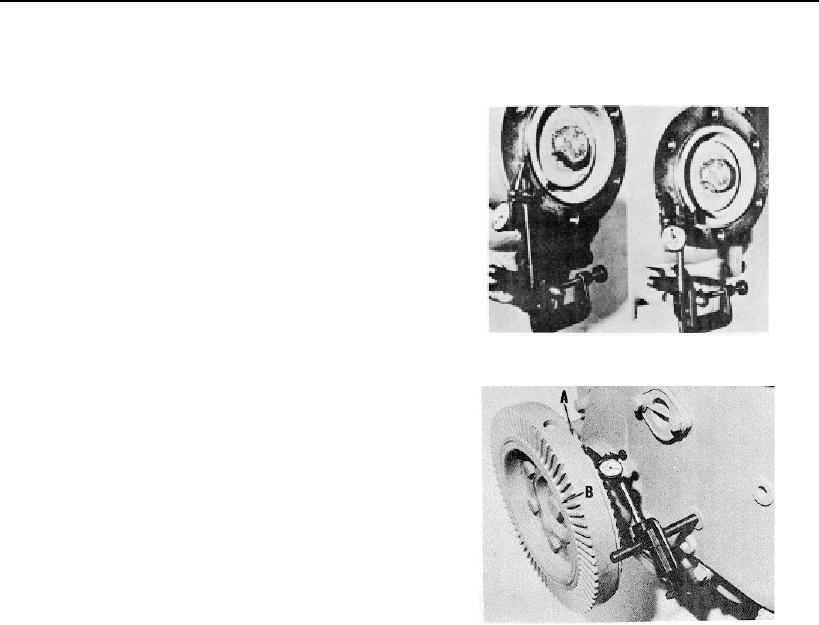
Fig. 1420, (N114156). Checking crankshaft flange
INSTALLATION
eccentricity and wobble
CAUTION
Lubricate crankshaft nose in flange area with SAE 30
rust preservative lubricant with 2 percent or higher
sulfated ash content DO NOT use lubricant when cast
iron flanges 115562, 115563, 175183 or 175185 are
used.
1. Install crankshaft flange over end of crankshaft. Center
line of key-way in flange and key-way in crankshaft
should be aligned within plus or minus 1/8 inch [3.18 mm]
.
2. Install retainer and capscrew, check current Parts
Catalog for correct capscrew and retainer, torque to
A. Outer Machined Surface
specifications listed in Table 14-1
B. Inner Machined Surface
3. With dial gauge mounted to gear case cover, check
Fig. 14-21, (N114140). Checking vibration damper run-
crankshaft flange eccentricity and wobble. Eccentricity
out
must not exceed 0.004 inch [0.10 mm] total indicator
reading; wobble must not exceed 0.003 inch [0.08 mm]
Vibration Damper And Pulley
measured at 2-3/4 inch [69.85 mm] radius. Fig. 14-20.
1. Position front engine support to block, if used, maintain
a minimum of 1/32 inch [0.79 mm] clearance between
4. Install vibration damper to crankshaft flange with
support and gear case cover. Tighten capscrews to 55 ft-
lockplates and capscrews. Torque to 60 ft-lb. [8.3 kg m]
lb. [7.6 kg m] torque.
and lock in place.
CAUTION
5. Position a dial gauge to gear case cover and rest arm
Do not use any lubricant on pulley or crankshaft mating
on outer machined surface at point (A, Fig. 14-21) to
surfaces.
Wipe
with
clean
dry
cloth.
check eccentricity and at point (B) on inner machined
surface of outer member to check wobble. Run-out must
403