
TRUCK SERVICE MANUAL
ENGINE
2. Use light finger pressure at the rocker lever contact
properly located.
surface to hold crosshead in contact with.valve stem
Compression Release Lever
nearest the push tube. Turn adjusting screw down until it
1. Install dowel in cylinder block if removed.
contacts its mating valve stem.
2. Position upper lever and bracket assembly to front
Note: With new crossheads and guides, advance
rocker arm housing and secure.
adjusting screw one-third of one hex to straighten stem in
3. Using screwdriver in slot in end of compression
its guide and to compensate for slack in threads. With
release shaft, turn shaft clockwise until lifting notch
worn crossheads and guides, it may be necessary to
contacts a valve push tube collar, move compression
advance the screw as much as 1/2 of hex in order to
release shaft lever to middle of travel; secure with
straighten the stem in its guide.
clamping screw.
3. Hold adjusting screw in position and torque locknut to
4. Secure spring on cylinder head with capscrew; hook
25 to 30 ft-lbs [3.5 to 4.1 kg m]; or, if ST-669 Torque
spring in lever on compression release shaft. Attach link
Wrench Adapter is used, tighten to 22 to 26 ft-lbs [3.0 to
to lower and upper lever; secure with' cotter pins.
3.6 kg m].
Fuel Pump/Compressor Drive/Accessory Drive
4. Check clearance between crosshead and valve spring
Bar 'engine to No. 1 cylinder, TDC position (firing
retainer with wire gauge. There must be a minimum of
stroke), continue rotating to 90 deg. ATC. In this
0.020 inch [0.51 mm] clearance.
position, the two center-punched marks on drive gear will
Rocker Lever Housing
mesh or index with two dash marks on camshaft gear.
1. Position new rocker lever housing gasket on cylinder
This timing. is required so external timing marks on
head.
accessory drive pulley will be properly aligned with timing
2. Loosen locknuts and back off rocker lever adjusting
mark on gear case to show valve and injector adjustment
screws two or three turns. Holding rocker levers in place,
positions, keyway of drive shaft will be at top. Secure
position housing on heads with ball ends of rocker levers
drive to cylinder block. Using a scrap gear case cover,
fitting into their respective push tube sockets. Install
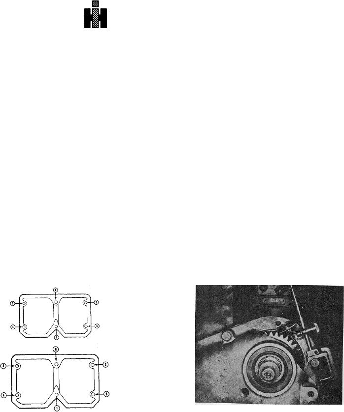
fabricated as illustrated in Fig. 14-10, check accessory
lifting brackets and fan hub bracket support bell crank, if
drive gear backlash.
1. Attach a dial indicator gauge to the block with plunger
used.
3. Secure housing, brackets and support with
on accessory drive gear tooth. Fig. 14-10. Rotate gear
capscrews. Torque in sequence, Fig. 14-9, to 55 to 65
as far as it will move to take up backlash, zero indicator.
ft-lbs [7.6 to 8.9 kg mi.
Fig. 14-10, (N114132). Checking accessory drive gear
backlash
Fig. 14-9, (N11463). Rocker lever housing torquing
2. Rotate gear in opposite direction and read backlash
sequence
on dial gauge. Backlash should be 0.0045 to 0.0105 inch
Note: On 80 deg. tilt engines use ST-1182 Valve Spring
[0.114 to 0.267 mm].
Spray Nozzle Locator to check that oil spray nozzles are
398