
TRUCK SERVICE MANUAL
ENGINE
Table 14-4: Flywheel Housing Specifications Inch [mm]
SAE No.
Bore Diameter (For Reference Only)
True Location Tolerance
Face Run Out Tolerance
00
31.000 to 31.010 [787.40 to 787.65 mm]
.012 [0.30 mm]
TIR
.012 [0.30 mm]
TIR
0
25.500 to 25.510 [647.70 to 647.95 mm]
.010 [0.25 mm]
TIR
.010 [0.25 mm]
TIR
1/2
23.000 to 23.008 [584.00 to 584.20 mm]
.010 [0.25 mm]
TIR
.010 [0.25 mm]
TIR
1
20.125 to 20.130 [534.27 to 534.40 mm]
.008 [0.20 mm]
TIR
.008 [0.20 mm]
TIR
2
17.625 to 17.630 [447.68 to 447.80 mm]
.008 [0.20 mm]
TIR
.008 [0.20 mm]
TIR
3
16.125 to 16,130 [409.58 to 409.70 mm]
.008 [0.20 mm]
TIR
.008 [0.20 mm]
TIR
4
14,250 to 14.255 [361.95 to 362.08 mm]
.006 [0.05 mm]
TIR.
.006 [0.05mm]
TIR
5
12.375 to 12.380 [314.33to 314.45 mm]
.006 [6.05 mm]
TIR
.006.[0.05 mm]
TIR
6
10.500 to 10.505 [266.70 to 266.83 mm]
.006 [0.05 mm]
TIR
.006 [0.05 mm]
TIR
Flywheel Housing
1. Clean mating surface of flywheel housing to block and
install new cork camshaft bore gaskets in flywheel
housing with gasket cement. Allow sufficient time for
drying.
Gasket slippage will allow oil to leak from rear of
camshaft bore.
2. If new flywheel housing is being installed, or if dowels
are worn, sheared or loose, remove dowels from block.
Snug housing to block with lockwashers and capscrews.
INDICATE FLYWHEEL HOUSING BORE
1. Draw chalk marks at 12, 6, 9 and 3 o'clock. Attach ST-
112 and a dial gauge to crankshaft flange. Fig. 14-14.
2. Check readings at 9 and 3 o'clock. If run-out exceeds
specifications in Table 14-4, move housing one-half of
Fig. 14-15, (N11448). Indicating flywheel housing face
distance to center horizontally.
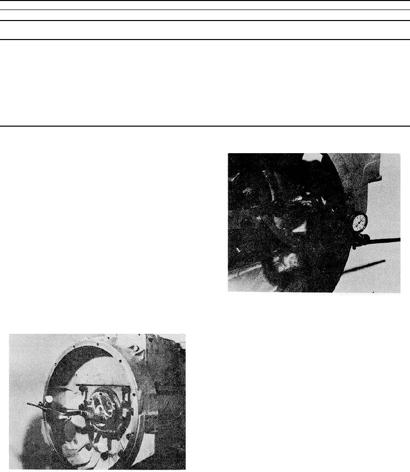
INDICATE FLYWHEEL HOUSING FACE
3. Check readings at 12 and 6 o'clock. If run-out exceeds
1. Attach ST-112 and a dial gauge as shown in Fig. 14-
specifications, move housing to center vertically.
15.
2. Push crankshaft forward to take up end clearance and
turn crankshaft to obtain readings on housing face. Take
up crankshaft end clearance in same direction each time.
3. Total flywheel housing tape run out must exceed
specifications in Table.14.4.
4. If both bore and face run-out readings are within limits
and dowels were removed, ream dowel holes to smallest
permissible oversize with ST-406 Drill Ream Fixture.
5. If necessary to correct for housing face run-out after
the bore has been aligned, remove housing and recheck
mating surfaces. Then reinstall, realign and dowel. After
readings are within limits, tighten capscrews alternately
Fig. 14-14, (N 11447). Indicating flywheel housing bore
and evenly to 150 ft-lb. [20.7 kg m] .
401