TM 5-3805-254-20-2
DUMP BODY CONTROL LEVER AND LINKAGE - CONTINUED
ACTION
LOCATION
ITEM
REMARKS
REMOVAL - CONTINUED
NOTE
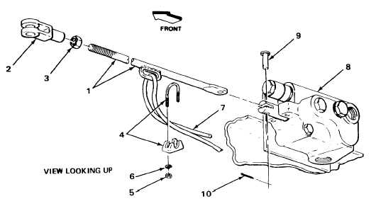
Count threads on rod before removing clevis, for correct adjustment when installing.
2. Rod (1)
Clevis (2)
Using two 8-inch slip-joint pliers, unscrew
and take off.
3.
Nut (3)
Using 3/4-inch open-end wrench and 8-
inch slip-joint pliers, unscrew and take off.
4. Clamp (4)
Two nuts (5) and
a. Using 7/16-inch box-end wrench, un-
two lockwashers (6)
screw and take off.
b. Get rid of lockwashers.
5. Cable (7)
Clamp (4)
Take off.
6. Control valve (8)
Cotter pin (10)
a. Using 6-inch long-nose pliers,
and clevis pin (9)
straighten ends and take out.
b. Get rid of.
7. Control valve (8)
Clevis pin (9)
Using 8inch slip-joint pliers, take out.
8.
Rod (1)
Take out.
TA244566
2-1368

