
TM 5-3805-264-13&P
0060
CLEANING AND INSPECTION
Clean and inspect components in accordance with General Maintenance Instructions (WP 0072) and the
following:
Inspect drive shaft and gearshaft for scoring or grooving on teeth. Any scoring, grooving, or burring of
outside diameter of teeth requires replacement of shafts as a set. If shafts are replaced, roller bearings
must also be replaced.
Inspect thrust plates for wear, pitting, or discoloration. If found, replace thrust plates.
END OF TASK
ASSEMBLY
WARNING
Eye protection and gloves must be worn when using grease or lubricating oils. Failure to
comply may result in personnel injury.
NOTE
Apply a light coat of lubricating oil to surfaces of components as they are assembled.
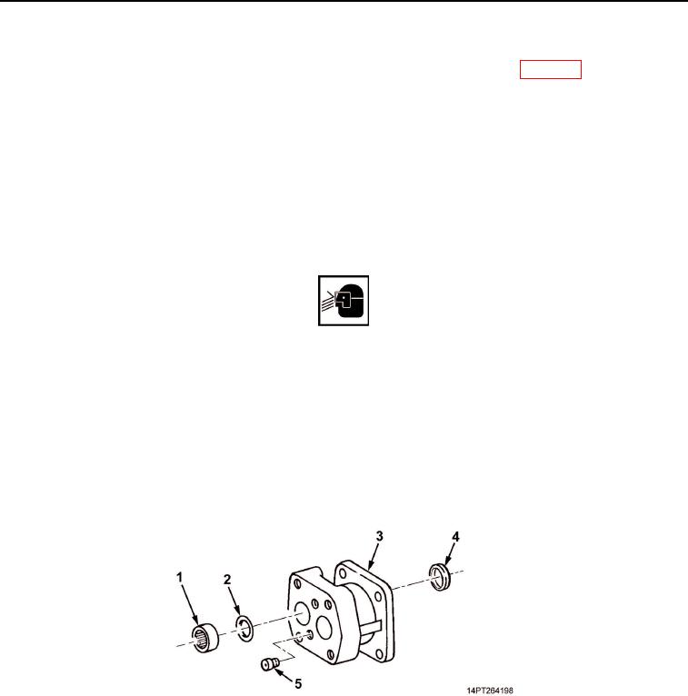
1.
Press two new ring seals (Figure 7, Item 2) and new roller bearings (Figure 7, Item 1) into end housing
(Figure 7, Item 3).
2.
Press new lip seal (Figure 7, Item 4) into drive shaft side of end housing (Figure 7, Item 3).
3.
Install two new check assemblies (Figure 7, Item 5) on end housing (Figure 7, Item 3).
Figure 7. Check Assemblies and Roller Bearings Installation.
03/15/2011Rel(1.10)root(maintwp)wpno(M1004926413)