
TM 5-3805-264-13&P
0060
DISASSEMBLY - Continued
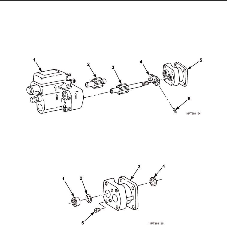
4.
Place hydraulic pump on clean, flat surface and separate end housing (Figure 3, Item 5) from gear housing
(Figure 3, Item 1).
5.
Remove drive shaft (Figure 3, Item 3) and gearshaft (Figure 3, Item 2) from end housing (Figure 3, Item 5).
6.
Remove thrust plate (Figure 3, Item 4) from end housing (Figure 3, Item 5). Remove six pocket seals
(Figure 3, Item 6) from thrust plate. Discard pocket seals.
Figure 3. Drive Shaft Removal.
7.
Remove two check assemblies (Figure 4, Item 5) from end housing (Figure 4, Item 3). Discard check
assemblies.
8.
Remove two roller bearings (Figure 4, Item 1), ring seals (Figure 4, Item 2), and lip seal (Figure 4, Item 4)
from end housing (Figure 4, Item 3). Discard roller bearings, ring seals, and lip seal.
Figure 4. Check Assemblies and Roller Bearings Removal.
03/15/2011Rel(1.10)root(maintwp)wpno(M1004926413)