
TM 5-3805-264-13&P
0060
ASSEMBLY - Continued
NOTE
Ensure that stud is installed in correct location as noted in disassembly.
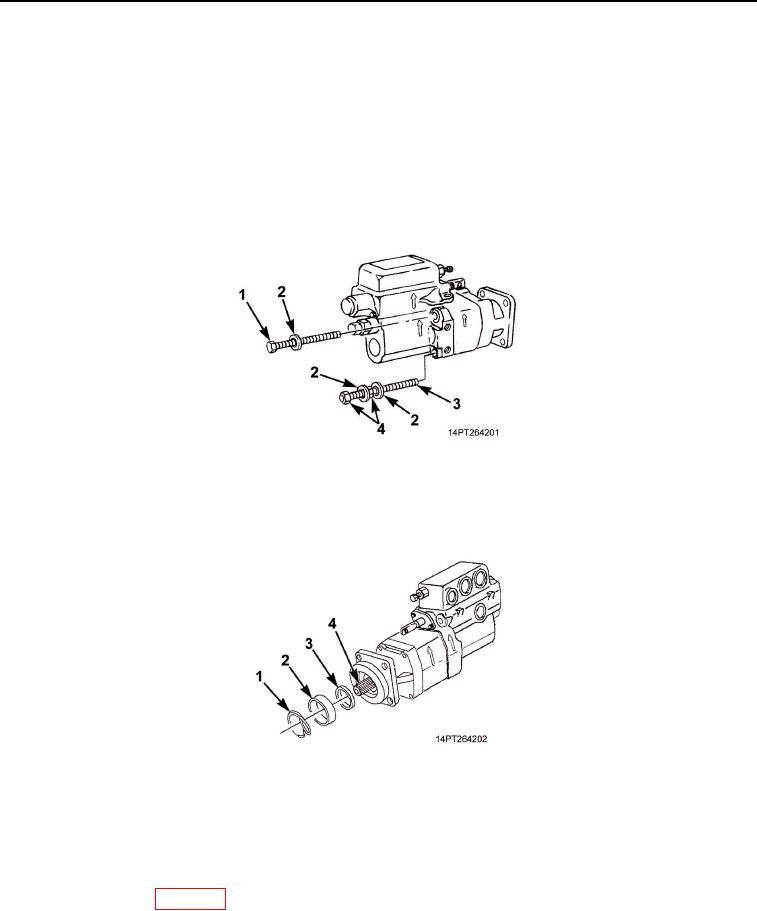
12.
Install three screws (Figure 10, Item 1), three washers (Figure 10, Item 2), stud (Figure 10, Item 3), washer
(Figure 10, Item 2), and nut (Figure 10, Item 4) in place to secure pump housings. Tighten screws and stud
in crisscross pattern and torque to 200 lb-ft (271 Nm). Check for free shaft movement by turning drive shaft
with a wrench.
13.
Install one washer (Figure 10, Item 2) and nut (Figure 10, Item 4) on stud (Figure 10, Item 3) and tighten by
hand.
Figure 10. Pump Hardware Installation.
14.
Install seal retainer (Figure 11, Item 3), spacer (Figure 11, Item 2), and new retaining ring (Figure 11, Item 1)
on drive shaft (Figure 11, Item 4).
Figure 11. Drive Shaft Retaining Ring Installation.
END OF TASK
FOLLOW-ON MAINTENANCE
Install hydraulic pump (WP 0059).
END OF TASK
END OF WORK PACKAGE
03/15/2011Rel(1.10)root(maintwp)wpno(M1004926413)