
TM 5-3805-264-13&P
0061
REMOVAL - Continued
NOTE
To ease installation, note mounting position of cable pivot pins and hold-down clamps prior
to disconnecting cables.
5.
Place transmission selector lever in D (Drive) position (TM 9-2320-363-10 or TM 9-2320-302-10).
6.
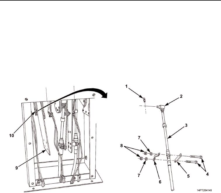
Tag transmission shift cable (Figure 3, Item 3).
7.
Remove two nuts (Figure 3, Item 8), washers (Figure 3, Item 7), screws (Figure 3, Item 4), clamp
(Figure 3, Item 6), and spacer (Figure 3, Item 5) from bracket (Figure 3, Item 9).
8.
Remove retaining pin (Figure 3, Item 1) from pivot pin (Figure 3, Item 2) and pivot pin from bracket
(Figure 3, Item 10).
Figure 3. Transmission Shift Cable and Components Removal.
03/15/2011Rel(1.10)root(maintwp)wpno(M1003826413)