• Home
  • Download PDF
  • Order CD-ROM
  • Order in Print
Figure 5. Hydraulic Control Cable and Components Removal.
Figure 7. Hydraulic Control Lever Removal.

Parts Manual For Truck, Dump, Heavy, Body M917A1 And M917A2
Page Navigation
  288    289    290    291    292  293  294    295    296    297    298  
img
.
TM 5-3805-264-13&P
0061
REMOVAL - Continued
17.
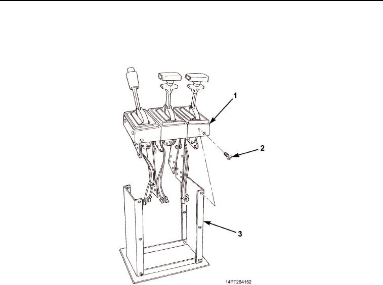
Remove two top screws (Figure 6, Item 2) from front and rear of shift tower (Figure 6, Item 3).
18.
Lift handle assemblies (Figure 6, Item 1) from shift tower (Figure 6, Item 3).
Figure 6. Handle Assemblies Removal.
0061-7
03/15/2011Rel(1.10)root(maintwp)wpno(M1003826413)


Privacy Statement
Press Release
Contact

© Copyright Integrated Publishing, Inc.. All Rights Reserved.