
TM 5-3805-264-13&P
0061
REMOVAL - Continued
9.
Place transfer case selector lever in N (Neutral) position (TM 9-2320-363-10 or TM 9-2320-302-10).
10.
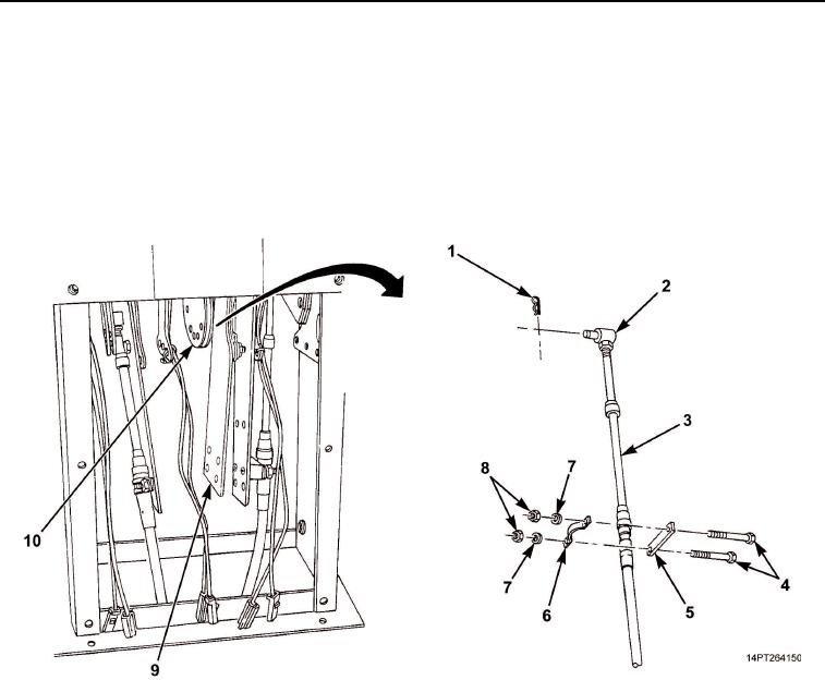
Tag transfer case shift cable (Figure 4, Item 3).
11.
Remove two nuts (Figure 4, Item 8), washers (Figure 4, Item 7), screws (Figure 4, Item 4), clamp
(Figure 4, Item 6), and spacer (Figure 4, Item 5) from bracket (Figure 4, Item 9).
12.
Remove retaining pin (Figure 4, Item 1) from pivot pin (Figure 4, Item 2) and pivot pin from bracket
(Figure 4, Item 10).
Figure 4. Transfer Case Shift Cable and Components Removal.
03/15/2011Rel(1.10)root(maintwp)wpno(M1003826413)