• Home
  • Download PDF
  • Order CD-ROM
  • Order in Print
Figure 6. Handle Assemblies Removal.
Figure 8. Hydraulic Control Lever Installation.

Parts Manual For Truck, Dump, Heavy, Body M917A1 And M917A2
Page Navigation
  289    290    291    292    293  294  295    296    297    298    299  
img
.
TM 5-3805-264-13&P
0061
REMOVAL - Continued
19.
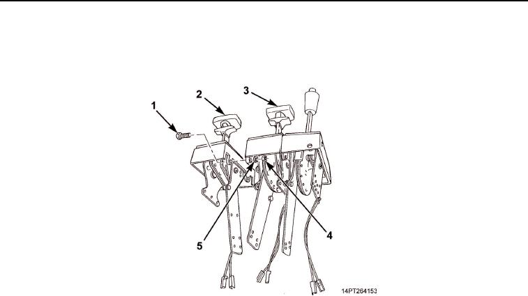
Separate hydraulic control lever (Figure 7, Item 2) from transfer case selector lever (Figure 7, Item 3) by
removing two bolts (Figure 7, Item 1), flatwashers (Figure 7, Item 5), and nuts (Figure 7, Item 4).
Figure 7. Hydraulic Control Lever Removal.
END OF TASK
0061-8
03/15/2011Rel(1.10)root(maintwp)wpno(M1003826413)


Privacy Statement
Press Release
Contact

© Copyright Integrated Publishing, Inc.. All Rights Reserved.