• Home
  • Download PDF
  • Order CD-ROM
  • Order in Print
Figure 8. Hydraulic Control Lever Installation.
Figure 10. Hydraulic Control Cable and Components Installation.

Parts Manual For Truck, Dump, Heavy, Body M917A1 And M917A2
Page Navigation
  291    292    293    294    295  296  297    298    299    300    301  
img
.
TM 5-3805-264-13&P
0061
INSTALLATION - Continued
2.
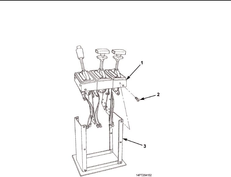
Position handle assemblies (Figure 9, Item 1) on shift tower (Figure 9, Item 3).
3.
To keep shift tower (Figure 9, Item 3) rigid, install two top screws (Figure 9, Item 2) on front and rear of shift
tower.
Figure 9. Handle Assemblies Installation.
0061-10
03/15/2011Rel(1.10)root(maintwp)wpno(M1003826413)


Privacy Statement
Press Release
Contact

© Copyright Integrated Publishing, Inc.. All Rights Reserved.