
TM 5-3805-264-13&P
0061
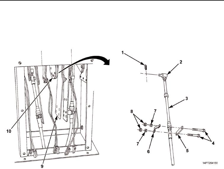
INSTALLATION - Continued
7.
Install transfer case control cable pivot pin (Figure 11, Item 2) in bracket (Figure 11, Item 10) and secure
with retaining pin (Figure 11, Item 1).
8.
Install spacer (Figure 11, Item 5), cable (Figure 11, Item 3), clamp (Figure 11, Item 6), two screws
(Figure 11, Item 4), washers (Figure 11, Item 7), and nuts (Figure 11, Item 8) on bracket (Figure 11, Item 9).
Figure 11. Transfer Case Shift Cable and Components Installation.
03/15/2011Rel(1.10)root(maintwp)wpno(M1003826413)