
TM 5-3805-264-13&P
0061
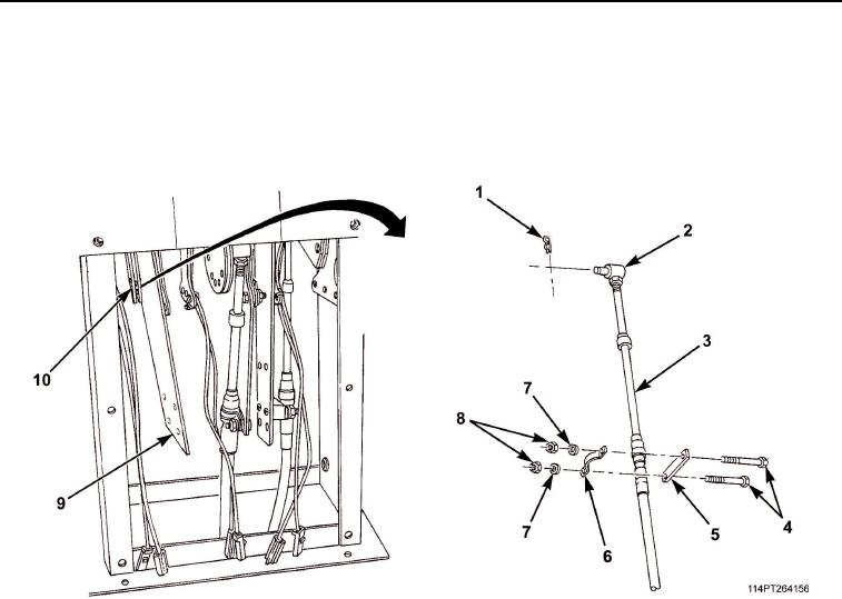
INSTALLATION - Continued
9.
With transmission selector lever in D (Drive) position, install transmission control cable pivot pin
(Figure 12, Item 2) in bracket (Figure 12, Item 10) and secure with retaining pin (Figure 12, Item 1).
10.
Install spacer (Figure 12, Item 5), cable (Figure 12, Item 3), clamp (Figure 12, Item 6), two screws
(Figure 12, Item 4), washers (Figure 12, Item 7), and nuts (Figure 12, Item 8) on bracket (Figure 12, Item 9).
Figure 12. Transmission Shift Cable and Components Installation.
03/15/2011Rel(1.10)root(maintwp)wpno(M1003826413)