
TM 5-3805-264-13&P
0062
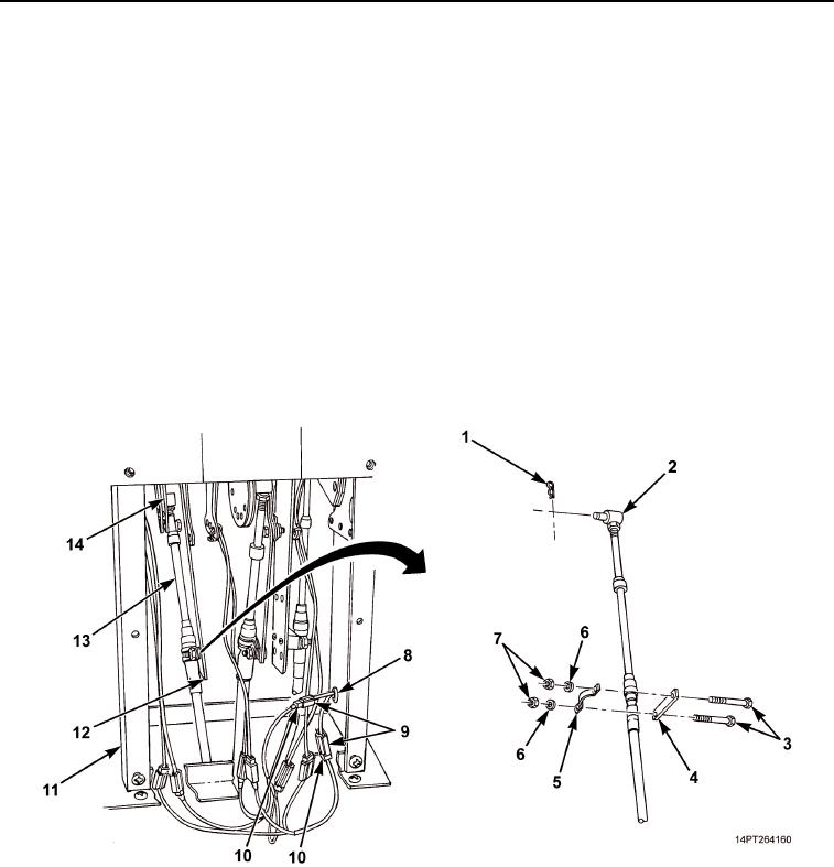
REMOVAL - Continued
4.
Tag and disconnect shift tower jumper harness power and ground connectors (Figure 2, Item 10) from cab
harness power and ground connectors (Figure 2, Item 9).
5.
Remove grommet (Figure 2, Item 8) and cab harness power and ground connectors (Figure 2, Item 9) from
shift tower (Figure 2, Item 11).
NOTE
To ease installation, note mounting position of cable pivot pins and hold-down clamps prior
to disconnecting cables.
6.
Place transmission selector lever in D (Down) position (TM 9-2320-363-10 or TM 9-2320-302-10).
7.
Tag transmission shift cable (Figure 2, Item 13).
8.
Remove two nuts (Figure 2, Item 7), washers (Figure 2, Item 6), screws (Figure 2, Item 3), clamp
(Figure 2, Item 5), and spacer (Figure 2, Item 4) from bracket (Figure 2, Item 12).
9.
Remove retaining pin (Figure 2, Item 1) from pivot pin (Figure 2, Item 2) and pivot pin from bracket
(Figure 2, Item 14).
Figure 2. Transmission Shift Cable Disconnection.
03/15/2011Rel(1.10)root(maintwp)wpno(M1003926413)