
TM 5-3805-264-13&P
0062
REMOVAL - Continued
14.
Place hydraulic control lever in DOWN position (WP 0005).
15.
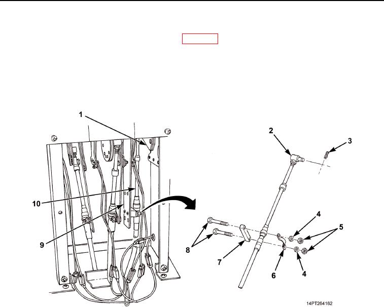
Tag hydraulic control lever cable (Figure 4, Item 10).
16.
Remove two nuts (Figure 4, Item 5), washers (Figure 4, Item 4), screws (Figure 4, Item 8), clamp
(Figure 4, Item 6), and spacer (Figure 4, Item 7) from bracket (Figure 4, Item 9).
17.
Remove retaining pin (Figure 4, Item 3) from pivot pin (Figure 4, Item 2) and pivot pin from bracket
(Figure 4, Item 1).
Figure 4. Hydraulic Control Lever Cable Disconnection.
03/15/2011Rel(1.10)root(maintwp)wpno(M1003926413)