
TM 5-3805-264-13&P
0062
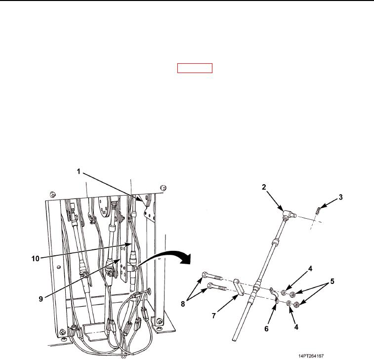
INSTALLATION - Continued
10.
Install spacer (Figure 9, Item 7), hydraulic control lever cable (Figure 9, Item 10), clamp (Figure 9, Item 6),
two screws (Figure 9, Item 8), washers (Figure 9, Item 4), and nuts (Figure 9, Item 5) on bracket
(Figure 9, Item 9).
11.
Place hydraulic control lever in DOWN position (WP 0005).
12.
By hand, push end of cable (Figure 9, Item 10) in as far as it will go and install pivot pin (Figure 9, Item 2) in
same hole in bracket (Figure 9, Item 1) as removed. If this cannot be achieved, perform Step 14.
13.
Release hand pressure from cable (Figure 9, Item 10). Force of hydraulic pump actuator will cause hydraulic
control lever to N (Neutral) position.
14.
Loosen nut at pivot pin (Figure 9, Item 2) and rotate pivot pin in desired direction. Tighten nut.
15.
Repeat Steps 12 through 14 until pivot pin (Figure 9, Item 2) can be installed in same hole in bracket
(Figure 9, Item 1) as removed with cable (Figure 9, Item 10) pushed in all the way. Install retaining pin
(Figure 9, Item 3).
Figure 9. Hydraulic Control Lever Cable Connection.
03/15/2011Rel(1.10)root(maintwp)wpno(M1003926413)