
TM 5-3805-264-13&P
0062
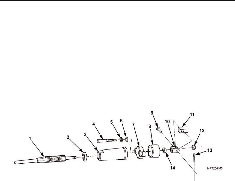
INSTALLATION
1.
Install nut (Figure 7, Item 14) onto cable (Figure 7, Item 1) same number of threads as removal.
2.
Slide cable bracket (Figure 7, Item 10) onto cable (Figure 7, Item 1) and install nut (Figure 7, Item 12).
3.
Position cable bracket (Figure 7, Item 10) onto hydraulic pump actuator (Figure 7, Item 11) and install clevis
pin (Figure 7, Item 9) and cotter pin (Figure 7, Item 13).
4.
Slide spacer (Figure 7, Item 8), screw bonnet (Figure 7, Item 3), and slide flange clamp (Figure 7, Item 7)
over cable bracket (Figure 7, Item 10).
5.
Install two screws (Figure 7, Item 4), flatwashers (Figure 7, Item 6), and washers (Figure 7, Item 5) on
flange clamp (Figure 7, Item 7).
6.
Slide jam nut (Figure 7, Item 2) onto cable (Figure 7, Item 1).
7.
Tighten jam nut (Figure 7, Item 2) against flange clamp (Figure 7, Item 7).
8.
Install transmission tunnel access cover (TM 9-2320-363-20-1, TM 9-2320-363-20-2, TM 9-2320-302-20-1,
or TM 9-2320-363-20-2).
Figure 7. Hardware Installation.
03/15/2011Rel(1.10)root(maintwp)wpno(M1003926413)