
TM 5-3805-264-13&P
0062
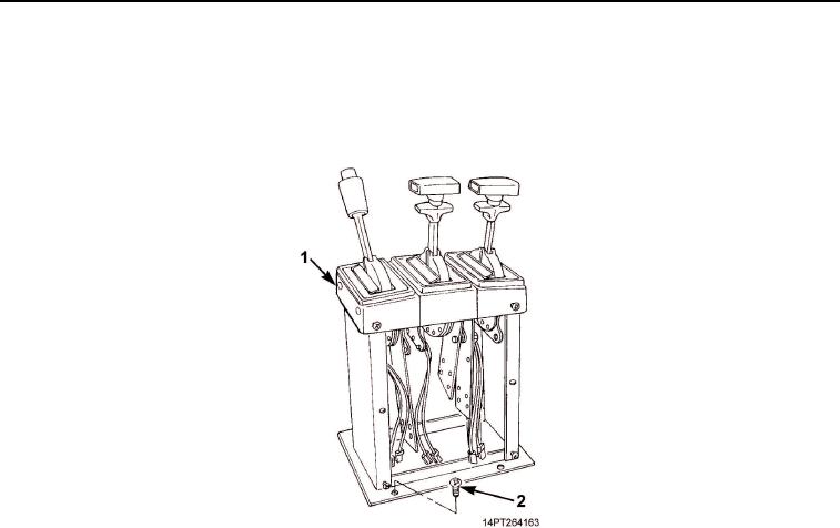
REMOVAL - Continued
18.
Remove four screws (Figure 5, Item 2) and shift tower (Figure 5, Item 1) from cab floor.
19.
Remove transmission tunnel access cover (TM 9-2320-363-20-1, TM 9-2320-363-20-2,
TM 9-2320-302-20-1, or TM 9-2320-363-20-2).
Figure 5. Shift Tower Removal.
03/15/2011Rel(1.10)root(maintwp)wpno(M1003926413)