Home
Download PDF
Order CD-ROM
Order in Print
Figure 7. Hardware Installation.
Figure 9. Hydraulic Control Lever Cable Connection.
Parts Manual For Truck, Dump, Heavy, Body M917A1 And M917A2
Page Navigation
305
306
307
308
309
310
311
312
313
314
315
TM
5-3805-264-13&P
0062
INSTALLATION
- Continued
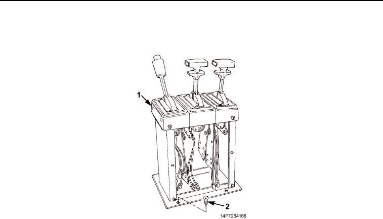
9.
Install
four
screws
(Figure
8,
Item
2) securing
shift
tower
(Figure
8,
Item
1) to cab
floor.
Figure
8.
Shift
Tower
Installation.
0062-9
03/15/2011Rel(1.10)root(maintwp)wpno(M1003926413)