
TM 5-3805-264-13&P
0062
INSTALLATION - Continued
18.
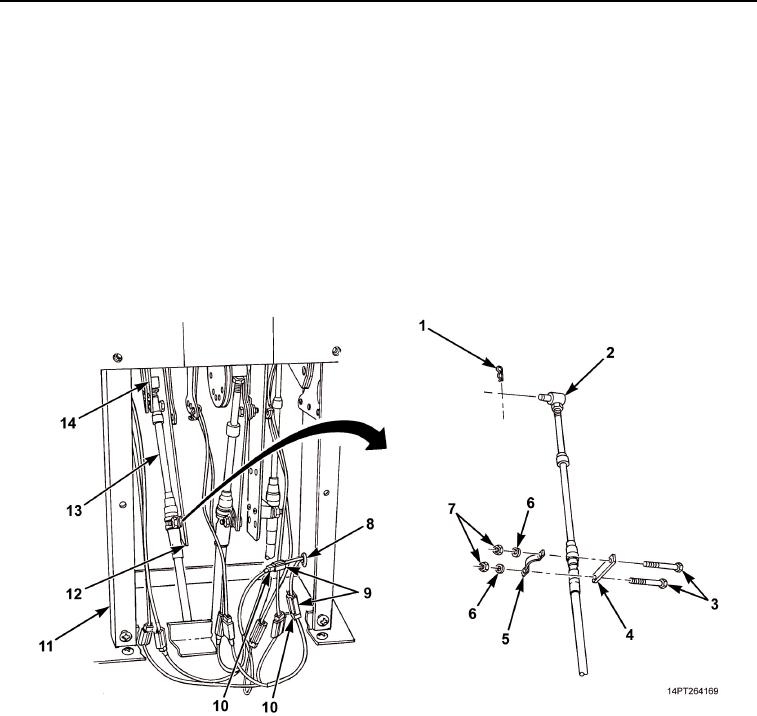
With transmission selector lever in D (Down) position, install pivot pin (Figure 11, Item 2) in bracket
(Figure 11, Item 14) and secure with retaining pin (Figure 11, Item 1). Remove tag from cable
(Figure 11, Item 13).
19.
Install spacer (Figure 11, Item 4), cable (Figure 11, Item 13), clamp (Figure 11, Item 5), two screws
(Figure 11, Item 3), washers (Figure 11, Item 6), and nuts (Figure 11, Item 7) on bracket
(Figure 11, Item 12).
20.
Place transmission selector lever in N (Neutral) position (TM 9-2320-363-10 or TM 9-2320-302-10).
21.
Feed cab harness power and ground connectors (Figure 11, Item 9) into shift tower (Figure 11, Item 11) and
install grommet (Figure 11, Item 8).
22.
Connect shift tower jumper harness power and ground connectors (Figure 11, Item 10) to cab harness
power and ground connectors (Figure 11, Item 9). Remove tags.
Figure 11. Transmission Shift Cable Connection.
03/15/2011Rel(1.10)root(maintwp)wpno(M1003926413)