
TM 5-3805-264-13&P
0060
ASSEMBLY - Continued
4.
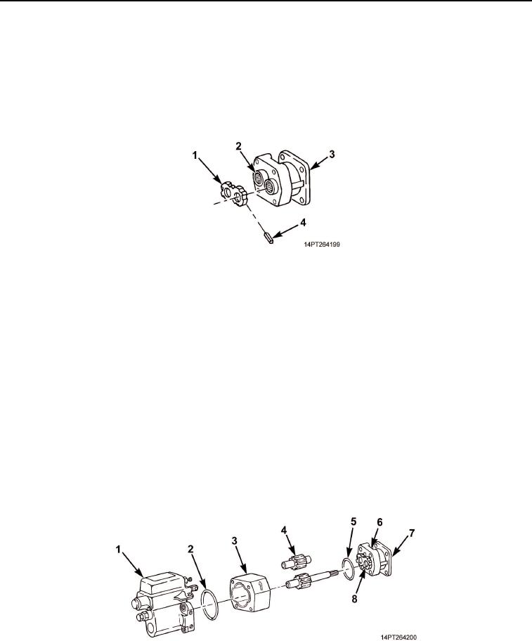
Cut two pocket seals (Figure 8, Item 4) 3/16 in. (4.8 mm) long and place in center slots of thrust plate
(Figure 8, Item 1). Use light grease to hold in place. Place thrust plate, with pocket seals facing machined
surface, over roller bearings (Figure 8, Item 2) of end housing (Figure 8, Item 3) and tap to about 1/32 in.
(0.8 mm) from machined surface.
5.
Insert remaining four pocket seals (Figure 8, Item 4) into place around thrust plate (Figure 8, Item 1). Tap
thrust plate down onto machined surface. Cut excess seal from thrust plate.
Figure 8. Pocket Seal Installation.
6.
Repeat Step 5 for thrust plate on pump housing (Figure 9, Item 1).
7.
Install pump housing (Figure 9, Item 1) in vise with machined surface facing up.
NOTE
Use scribe marks from disassembly to properly assemble pump housings. Light tapping
with rubber hammer may be required to seat housings in place.
8.
Install new gasket seal (Figure 9, Item 2) in gear housing (Figure 9, Item 3) and place gear housing on
pump housing (Figure 9, Item 1).
9.
Install drive shaft (Figure 9, Item 5) and gearshaft (Figure 9, Item 4) into gear housing (Figure 9, Item 3).
Check for free turning of gears.
10.
Install new gasket seal (Figure 9, Item 6) on gear housing (Figure 9, Item 3). Apply light coat of grease to
drive shaft (Figure 9, Item 5).
11.
Place end housing (Figure 9, Item 7) over drive shaft (Figure 9, Item 5) and carefully press housing in place,
seating gears against thrust plate (Figure 9, Item 8).
Figure 9. Gear Housing and Drive Shaft Installation.
03/15/2011Rel(1.10)root(maintwp)wpno(M1004926413)