TM 5-3805-264-13&P
0060
DISASSEMBLY
1.
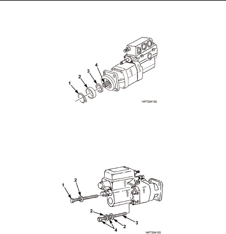
Remove retaining ring (Figure 1, Item 1), spacer (Figure 1, Item 2), and seal retainer (Figure 1, Item 3) from
drive shaft (Figure 1, Item 4). Discard retaining ring.
Figure 1. Drive Shaft Retaining Ring Removal.
2.
Secure hydraulic pump in vise and remove three screws (Figure 2, Item 1), two nuts (Figure 2, Item 4), and
five washers (Figure 2, Item 2) securing pump housings.
NOTE
Note stud location for assembly.
3.
Remove stud (Figure 2, Item 3).
Figure 2. Pump Hardware Removal.
CAUTION
Internal surfaces and parts of hydraulic pump are machined to strict manufacturing
tolerances. Care must be taken not to damage machined surfaces. Failure to comply may
result in damage to equipment.
NOTE
Drive shaft and gearshaft may slide out with end housing.
03/15/2011Rel(1.10)root(maintwp)wpno(M1004926413)

