
TM 5-3805-264-13&P
0066
ASSEMBLY - Continued
NOTE
Apply a light coat of lubricating oil to surfaces of components as they are
assembled.
Assemble hydraulic cylinder starting with the largest diameter sleeve and working
inward.
1.
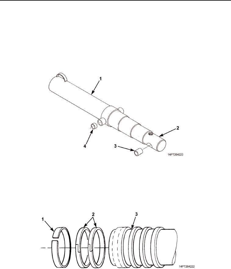
If removed, install two bushings (Figure 20, Item 4) in barrel (Figure 20, Item 1) and bushing
(Figure 20, Item 3) in plunger (Figure 20, Item 2).
Figure 20. Bushing Installation.
NOTE
Perform Steps 2 through 7 to install largest diameter sleeve.
2.
With hydraulic cylinder components in horizontal position, install two piston rings (Figure 21, Item 2) and
new wear ring (Figure 21, Item 1) on sleeve (Figure 21, Item 3).
Figure 21. Wear Ring and Piston Ring Installation.
03/15/2011Rel(1.10)root(maintwp)wpno(M1005126413)