TM 5-3805-264-14&P
5-2.
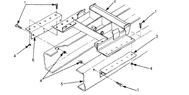
CYLINDER SUPPORT FRAME REPLACEMENT (Con’t).
2.
Remove 24 locknuts (4), screws (1), left angle bracket (3), and right angle bracket (6) from cylinder support
frame (2) and vehicle chassis (5). Discard locknuts.
3.
Remove cylinder support frame (2) from vehicle chassis (5) and move frame to safe work area. Remove
Use extreme caution when handling heavy parts. Keep clear of heavy parts sup-
ported only by lifting device. Failure to follow this warning may cause death or
injury to personnel or damage to equipment.
1.
Attach slings to cylinder support frame (2) and attach slings to lifting device. Take up slack in slings with lift.
2.
Lift cylinder support frame (2) and position on vehicle chassis (5).
3.
Install right angle bracket (6) and left angle bracket (3) to vehicle chassis (5) and cylinder support frame (2)
with 24 screws (1) and new locknuts (4).
4.
Torque locknuts (4) to 200 lb.-ft. (271 N•m).
FOLLOW-ON TASKS:
Install hydraulic cylinder (paragraph 5-6).
Install hydraulic reservoir (paragraph 4-73).
Install body up switch (paragraph 4-38).
5-8